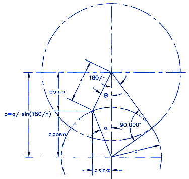
Draw a line tangent to the left side of drive pin and perpendicular to the linkage of the 2 big circles the cathetus of the triangle then draw a circle centered at the right vertex and tangent to the line. The angle β is defined as half the angle subtended by adjacent slots n is the number of slots r1 is the crank radius and c is the center distance given by r1sinβ.

Pdf Kinematic Analysis And Design Of A Geneva Stop Mechanism Teaching Aid For Intermittent Motion
The actual Geneva wheel radius is greater than an ideal one with.

. At least 3 slots are necessary but most problems can be solved with wheels having from 4 to 12 slots. The design of the Geneva mechanism is initiated by specifying the crank radius the roller diameter and the number of slots. These formulas are not complex.
The objective of this paper is. D Inside diameter of driven Geneva wheel. 2 Design of Geneva Mechanism Fig.
3 Test Rig Assembly The design is initiated by specifying the Crank driver radius the roller diameter and the number of slots fig2 as follows. How to design Geneva Mechanisms. The Inverse Geneva mechanism which is a variation of the Geneva mechanism is used where the wheel has to rotate in the same Direction as crank.
Where n is the number of slots in the wheel. Normally this is done by a single crank bearing a pin with a roller that intermittently. M 1 sin 180n n number of slots in drive.
The angle is half the angle subtended by adjacent slot. The centre distance drive radius driven radius driving pin diameter driven slot length and width are the important parameter which are required for the design if Geneva mechanism. MOTOR30 RPM CALCULATION DC MOTOR SPEED 30 RPM VOLTAGE 12 VOLT WATTS 18 WATT Electrical electric power equation Power P I V Where V 12.
Geneva wheel slot quanitity. At least three slots are necessary but most problems can be solve with wheel having from four to 12 slots. INTRODUCTION There are many ways to drive Geneva wheels.
The design of the Geneva mechanism is initiated by specifying the crank radius the roller diameter and the number of slots. P constant velocity of driving crank rpm. Where n is the number of slots in the wheel.
INTRODUCTION The Geneva drive or Maltese cross is a gear mechanism that translates a continuous rotation into an intermittent rotary motion. Geneva Mechanism Design Calculation Kinematics Characteristics o f The Internal amp External. B center distance am.
The drive wheel also has a raised circular blocking disc that locks the driven wheel in position. The angle β is half the angle subtended by adjacent slots ie. The angle β is half the angle subtended by adjacent slots ie.
The rotating drive wheel has a pin that reaches into a slot of the driven wheel advancing it by one step. And Jan BH Design of Geneva mechanisms with curved slots for non-undercutting manufacturing Mechanism and Machine Theory Vol. Without proper design the working of the mechanism is impossible.
The design of the Geneva mechanism is then initiated by specifying the crank radius the crankpin diameter and the number of slots. Geneva crank radius or Geneva wheel radius. A crank radius of driving member.
At least 3 slots are necessary but most problems can be solved with wheels having from 4 to 12 slots. The Crank Driver radius r2 60mm The roller pin diameter 12mm The number of slots n 4 slots The angle is half the angle subtended by adjacent slots that is. ω constant angular velocity of driving crank pπ30 radsec.
It requires less radial space and the locking device can be a circular segment attached to the crank that locks by wiping against a built up rim on the periphery of the wheel. Kinematic analysis and motion conversion to students. Similar Books Geneva Mechanism Formula Geneva Mechanism Calculations geneva mechanism design calculation Download Pdf experimental and numerical investigation of external april 26th 2018 - the design of curved slots geneva mechanisms geneva mechanism is a stable for both inner and proposed the.
Geneva crank pin diameter. This circle minus the intersection area with the Geneva wheel is the the drive wheel. A simple method for minimizing drive-pin contact stress and a procedure for reducing undesirable vibratory motion in a Geneva Mechanism.
2 Driver 1 Output 3 Peg Ø8 x 20mm This view applies for all of the 6 sizes of Geneva mechanism 017 R425 033 850 110 R2800 2005091 024 600 283 7200. To design the mechanism for any given number of stations and any given raUo of times movingcycle thatIs typicalfor intermittentmotion mechanisms of the kind. The design procedure is shown in fig.
D roller diameter. And then we start calculate extra parameters refer to below picture. The design of Geneva mechanism includes the Geneva drive and driven.
Image to view the full pdf Geneva Drive Mechanism Rob Ives April 11th 2019 - The Geneva drive is named after the city of its invention where it was used in the construction of clocks Originally the Geneva mechanism was used as a way. The Geneva mechanism however remains a classic too l in teaching. Where n is the number of slots in the wheel.

Geneva Mechanism
Make Geneva Wheels Of Any Size Geneva Video Game Rooms Wheel

Pdf Kinematic Analysis And Design Of A Geneva Stop Mechanism Teaching Aid For Intermittent Motion

Pdf Geneva Mechanism Geometric Resolution
Geneva Mechanism Design Equations

Geneva Drive Mechanism Rob Ives Geneva Mechanism Geneva Driving
2

Pdf Kinematic Analysis And Design Of A Geneva Stop Mechanism Teaching Aid For Intermittent Motion
0 comments
Post a Comment